
In speaking with our customers, and browsing various automotive forums – I have observed a lot of confusion and misinformation concerning hydraulic lifter operation and preload specification.
I have concluded it may be helpful to provide some information on this subject.
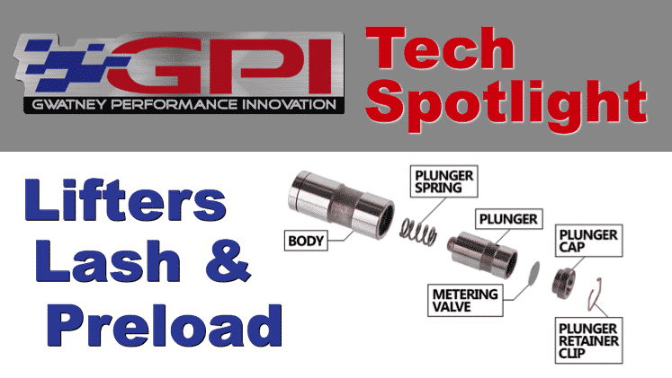
Anatomy of a Hydraulic Lifter
A hydraulic lifter isn’t too complicated. It consists primarily of a body, plunger and check valve.
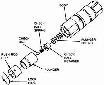
The body has an oil feed passage and the plunger has an undercut which aligns with the feed hole regardless of the plunger’s position in the body or “preload position”. The oil is then feed into two cavities’, one under the plunger sometimes referred to as the pressure chamber, and the other inside the plunger which acts as a reservoir. When the valve is closed oil is fed thru the one-way check valve into the pressure chamber where it maintains 0 valve lash by filling the area between the plunger and the bottom of the lifter body.

As the cam lobe acts upon the lifter to open the valve, the valve spring tries to force the oil back out of the pressure chamber causing the check valve to close off the passage back to the reservoir. Because a liquid doesn’t compress, the lifter body and plunger essentially become one solid unit providing normal actuation of the valve train. This self-adjusting component provides compensation for normal wear and more importantly changing clearances due to expansion and contraction of engine components throughout varying operating temperatures.
Bleed Down & Pump Up Explained
Terms like “bleed down” and “pump up” are sometimes used during lifter discussions. For all our budget conscious readers you may want to skip the next paragraph as I am about to take away your innocence as it relates to bargain lifters. Ignorance is bliss and what you don’t consider won’t hurt you as you stare into the tail lights of a competitor.
Ignorance is bliss and what you don’t consider won’t hurt you as you stare into the tail lights of a competitor.
Bleed down generally relates to the oil in the compression chamber escaping between the outer wall of the plunger and the inner wall of the body. This is a necessary feature designed into the lifter to allow it to essentially self-adjust each time the valve is cycled. The bleed down rate is determined by the lifters internal clearance meaning machining tolerance must be held to a very high standard. The materials and processes used to achieve this is reflected in the price of a high-quality performance lifter. A small percentage of the lift and duration ground into the camshaft is absorbed by the hydraulic lifter by design so it deserves consideration when choosing a lifter. Many enthusiasts haggle for days over the cam selection only to mate it with the deal of the week bargain lifter. Depending upon tolerance variation they could well be operating their valve train at 16 different lift and duration specs.
Pump up is normally not the lifters fault. Think about it, oil being fed thru an orifice into a chamber of a fixed dimension. How can that go wrong? Here is a way, the valve is heavy, the valve spring is weak, the cam lobe is aggressively actuating the valve in a manner similar to a baseball pitcher throwing a fastball. In this scenario, the valve shoots off the top of the lobe as it tries to steal a kiss from the piston. The valve spring finally gets a handle on it only it’s now opened more than it should have. The lifter recognizes this and does its job by removing the lash. Now the valve comes down the backside of the ramp on its way back home only to find it can’t close the door because the lifter is now too long by, oddly enough about the same distance as the valve went flying out of control. I hope this puts it in perspective and is more entertaining than staring at spintron data, but the point is, control the valve and the poor misunderstood lifter can do its job.
What exactly is “Preload”?
Now that we have a better understanding of the lifter and its operation let’s explore preload.
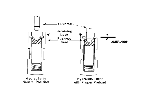
I would define preload to be the distance the lifter plunger travels from its full extension to its operating position when the valve is fully closed, and all lash has been removed.
I see a lot of misinformation relating to LS engines counting turns after zero lash which is fine for standard travel lifters so long as you get the math right. Many times, I see people declaring that the threads per inch equates to the plunger travel without entering the rocker arm ratio into the equation. The first question that should be asked is – what is my total lifter plunger travel? Most quality lifter manufacturers publish this spec. Most short travel lifters are around .060 more or less while a GM LS7 lifter commonly used has .200 travel. If you can’t find a spec on your lifter an easy way to find out is to place a dial indicator on the pushrod end of the rocker arm with cam lobe on its base circle. Hand thread the rocker arm retainer bolt until all lash is removed. Now zero the dial indicator and tighten the rocker retaining bolt. You will see the dial indicator needle start moving as the valve spring pressure bleeds the lifter down. When the needle stops, assuming the lifter hasn’t bottomed out, the movement recorded by the dial represents the current preload. Next use a non-serrated smooth flat screw driver blade to insert between the valve stem and the rocker arm. Use the taper of the blade to gently bleed the oil from the lifter which allows measuring the remaining plunger travel. When the needle stops the total measurement recorded by the dial will represent the total lifter travel.
Now that we know how to measure preload and travel let’s discuss the pros and cons of various preload set ups. In our experience an aluminum block LS engine as it expands with heat to operating temperature will gain .012 to .015 in valve lash. Iron blocks will gain .008 to .010. This means if we installed a push rod yielding .030 preload cold, at operating temperature we would have .015 to .018 remaining for wear allowance. The reason one may want to run a minimum preload set up such as this, would be when a tight piston to valve clearance exists. Let’s say it’s a LS3 manual trans car. We have milled the heads for additional compression and have calculated the piston to valve clearance at .040. If we only have .018 of travel remaining and we miss a gear and float to valves, the plunger can only reduce that clearance to .022. If we were running a max preload set up in this instance, we would make unwanted contact. This is all hypothetical, in reality, lifter “squish” and valve train deflection would increase the clearance even more, but we prefer to consider that a safety margin. The other potential advantage is, if you were to float the valves it would create a less dramatic power reduction and would recover faster, not that we ever recommend valve float.
Now let’s explore a max preload set up. As mentioned earlier, a hydraulic lifter absorbs part of the lift and duration as a normal function. Let’s say you want your hydraulic valve train to act more like a solid. Increase the valve spring pressure and set the preload near the bottom. At operating temp in this case, you only have .012 to .015 to lose. This is the main principal behind a short travel lifter is, you can’t give up what you don’t have. This is something you may do if you were racing where hydraulic lifters were a class rule and you were looking for every advantage, otherwise by the time you go to the trouble of getting the travel this exact you may as well just go with a solid roller.
If you are running a cam that doesn’t create tight piston to valve clearance or if you have aftermarket pistons with valve reliefs, the lifter doesn’t particularly care where it operates within its range of plunger travel. As long as it has adequate remaining travel to compensate for expansion, contraction and a little normal valve seat, stem, rocker and pushrod wear over time it will happily do its job of maintaining 0 lash.
In Conclusion
I hope this helps alleviate some valve train drama. I will include some GPI recommendations below for quick reference. All the best, and thanks for your support.
Quick Reference Guide
Rocker arm retainer turns to preload :
- LS rocker bolt 8mm x 1.25 = 20.32 threads per inch
- 1”/ 20.32 = .0492 trunion movement per turn of the rocker retainer
- .0492 applied to appropriate formula=.078 lifter preload per turn for a (1.7) rocker
- .0492 applied to appropriate formula =.076 lifter preload per turn for a (1.8) rocker
Lifter Travel:
- GM LS7 Lifter plunger total travel = .200
- Johnson (standard travel) 2110 or 2120 Lifter total travel = .215
- Most short travel lifters =.050 to .060 best to test the lifter being used as they leave little room for error
GPI recommended preload for most cams and aftermarket pistons with valve reliefs:
- = min .050, max .130 or (¾ to 1 ¾ turns)
Recommendations for applications where piston to valve clearance is tight:
- = min .025, max = .020 greater than minimum PTV clearance. Example: if the measured PTV is .030, your preload should be .025 to .050. (not as critical in auto trans applications where mechanical overrev is less probable) ref paragraphs 7 and 8
Great article. Just what I needed to read. Thanks
My name is Sam…
I’m running a LS Gen 3, 5.3 iron block with a balanced Gen 4 rotating assembly. 799 cathedral port heads. LS7 lifters with a BTR 4.8 stage 2 turbo cam. It has .607 intake lift and .619 exhaust lift. My pushrods are 7.400 length 5/16 biameter with a 0.80 wall. Will this set up work with twin turbos…?
Sam in theory it should work fine, you have a strong enough pushrod, but the length I cannot confirm for you with the info that was given. It should be close but I do suggest you verify with the process mentioned in this article.
Stock Gen 4 pistons and rods 6.098 rod length
Thanks for the great explanation. I have one additional question please:
Does changing from minimum preload to maximum preload have a noticeable affect on idle quality/vacuum? Or does the plunger “Squish” effect primarily show up only when valve train inertia loads and RPM are high?
The squish you will get will mainly be at higher loads. At idle, the preload will not effect vaccum. The more the preload (less area to squish), the more power it will make. With that also comes more area for the lifter to pump up if you run outside where your valvetrain is stable! (AKA FLOAT).
Hello, I would like to ask a question for preload recommendations. I have LS L99 converted to ls3 with Texas speed PRC racing heads milled at .38 with ls7 lifters with trinium rebuild
stock rockers and a Texas speed mild cam. What would be a safe preload range for my lifters? Thanks!
Anyone know what the preload is on a GM 350 ho4 290 hp engine is from 0 lash. Cant find it anywhere
What is the clearance between the piston and the lifter bore on a sbc lifter? Can this vary from lifter to lifter in a lot of 16? Does this matter if it’s a super tight or some what loose? Like turn the lifter over and the piston slides out (cleaned and dry). No wear on face of lifter. 70k miles on engine.
In your above quick ref guide a 1.8 gives less preload than a 1.7? What math are you using? I get .078 with a 1.6 rocker.
Here is the math, remember , the long end of the rocker is acting upon the valve tip which in the case of preload is fixed.
=SQRT((((1+F3)^2)+((1+F3)^2))-(2*(1+F3)*(1+F3)*(COS(ACOS(((C6^2)-((F3^2)+(F3^2)))/(-2*F3*F3))))))
Sometimes with light valve springs it takes a little while for the lifter to bleed down. If that particular lifter acts differently it’s either a lifter or spring problem.
I have a 1999 350 Vortex that has a lifter that will not compress. When I adjust to zero lash, and then turn an additional turn, the valve opens up. Is it possible that the check valve in the lifter is plugged up?
Nope. The bleed down only occurs from oil leaking between the plunger and the body.