
INTRODUCTION
Welcome back to Part 2 of our discussion on late model GM gearing and converter choices (want to read the Part 1 on Manual setups? Click Here). This series is aimed to help answer the popular “which gear and converter should I run in my car” which populates social media and technical forums on a near daily basis. The “gears” piece of this question refers to the final drive ratio of the car determined by the ring and pinion ratio of the rear differential. The “converter” piece of this question refers to the coupler between the engine and automatic transmission. These discussions often lack key information about the car in question – which transmission it has, the motor combination, vehicle weight, how the vehicle is used, and are usually filled with replies with more than a few bits of mis-information. More often than not this leaves the original asker even more unsure of what will work best for their combination. We are here to help!
GM has offered several automatic transmissions throughout the years. This article intends to specifically consider the 6L80E/6L90E, but the principals explains within apply to most all automatic transmissions. The 6L80 represents an evolutionary step forward for GM in increasing the overall ratio spread (difference between lowest and highest gear ratio), and paved the way for even more aggressive eight and ten speed transmissions with incredible ratio spreads. A manual TR6060 “M10” has a ratio spread of 5.38, compared to GMs trusty 4L80 automatic which has a ratio spread of just 3.31. The 6L80 has spread of 6.01, 12% broader than the TR6060, and a whopping 82% broader than the 4L80. Out of scope in this discussion but worth a mention is the 10L80/90 in the newest SS/1LE/ZL1 Camaros, which has an absolutely incredible spread of 7.34! This gives insight into why the aftermarket has declined to develop different final drive ratios for late model cars with 8 and 10spd transmissions – they simply are not needed.
GEARS AND CONVERTER – HOW THEY WORK:
First, if you missed it in part one, gears are basically a series of circular levers that mesh together to provide the constant transmission of rotary power. When you pair a smaller drive gear with a larger driven gear you trade RPM for torque on the driven gear. If the drive gear is half the diameter of the driven gear, the driven gear will produce half the RPM, but twice the torque of the driven gear. When we increase the final drive ratio (ring and pinion found in the rear differential) in a car we are trading rpm for torque, which translates into stronger acceleration.
The torque converter is perhaps one of the least understood, and most critical pieces of the driveline in an automatic car. Unlike a manual transmission car, which uses a clutch to mechanically connect and disconnect the engine from the transmission, the torque converter creates a fluid coupling from the engine to the transmission. This coupling has a variable amount of slippage, which allows for the engine to turn at idle (or greater) speed while the transmission input remains stopped. This allows an automatic car to come to a stop while in gear. It also has the incredible ability to multiple torque, which is a decisive advantage when accelerating a racecar! Stay with me for the next few paragraphs and you’ll soon have a better understanding of this incredible piece of hardware.
TORQUE CONVERTER – DEEPER DIVE:
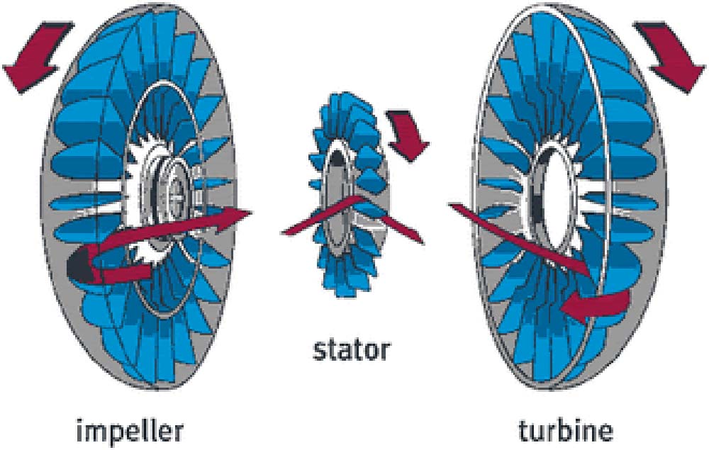
Perhaps the easiest way to understand this unique fluid coupling design is to imagine two fans – one attached to the engine crankshaft (the impeller) and directed at its counterpart, which is attached to the transmission input shaft (the turbine). As the engine turns at idle its fan generates a gentle breeze which in turn will blow against the fan on the transmission input shaft. If the breeze is strong enough, then the transmission will turn, albeit at a slower speed. As the engine speed increases, so does the gentle breeze, become more of a hurricane. This imparts more force against the fan on the transmission, and increases the power and rpm delivered to the transmission.
However, the fan metaphor doesn’t fully do justice to the torque converter – as unlike the open air fan analogy, the torque converter is an enclosed system using fluid and not air. The fluid is not simply blown straight from the impeller (driven by the engine) to the turbine (drives the transmission). As the impeller and impeller housing rotate they create a centrifugal force, throwing fluid from the middle of the impeller outward where the shape of the impeller housing and impeller blades direct it forcefully against the turbine blades. The turbine blades are angled in such a way to best harness this energy, which in turn creates rotational force to drive the transmission.
There is another key component of the torque converter that plays an essential role in managing the fluid flow inside of the converter – the stator. To this point, in the system we’ve described we’ve used centrifugal force to drive fluid outwards from the impeller and into the turbine, which has blades of an opposing angle to best capture the energy being transferred. We now have fluid in the turbine moving at high speed that needs to return to the impeller to repeat the cycle. The problem is that as described above, the blades of the turbine are opposed to those of the impeller, and the impeller is turning faster than the turbine. If we allow the fluid to flow straight from the middle of the turbine back to the middle of the impeller we would waste much of the centrifugal force we created, negating our torque multiplication. The stator is used to redirect the fluid exiting the turbine, aiming it at the backside of the impeller fins where it can apply more of its energy in turning the converter, rather than giving up that energy, or worse impeding motion. This redirection and recapturing of energy is a key component of the torque multiplication that makes the torque converter such an incredible asset to a drag car.
However the stator has one more trick to deliver. The stator is mounted to the transmission input shaft with a 1-way sprag clutch, which allows for it to only rotate in one direction, with the turbine. When the converter is under high slippage, the stator will not freewheel at all, as the force of the fluid flow from turbine to impeller holds it locked against the sprag clutch, synchronizing it’s RPM with the turbine. However, as the rpms of the engine and converter increase, the difference in impeller and turbine speed will diminish. As the rate of slip drops, the force against the stator decreases, and will eventually reach a point where the stator will freewheel faster than the turbine to direct fluid more efficiently back into the impeller. Without this freewheeling, the stator would become an impediment to fluid flow when impeller and turbine are near the same speed.
The final component of a torque converter is the lock-up clutch. This is a mechanical clutch much like that found in a manual transmission car, hydraulically controlled by the transmission, which will lock the impeller and turbine together, resulting in a 1:1 coupling of input and output speed. This is primarily done in production cars to increase efficiency at cruising speeds, where torque converter slip represents an inefficiency. Locking the converter can improve fuel economy and engine and transmission longevity by eliminating slippage and excess heat production while lowering cruising rpm. These OEM applications utilize a fairly small amount of friction material in the lockup clutch to transmit energy – as the applications are designed only to hold cruising power. Aftermarket torque converters offer the opportunity for the use of multiple clutch disks with much more friction material capable of holding high horsepower, and even transitioning from an unlocked to a locked state under full throttle. This creates some interesting opportunities to further increase vehicle performance by locking the torque converter under certain performance driving conditions.
SELECTING A TORQUE CONVERTER:
Torque converter selection is one of the most important components of any build, as the right characteristics will dramatically enhance performance by optimizing the torque multiplication, stall speed, responsiveness, and drivability.
One of the biggest reasons a torque converter change is required is to accommodate an aftermarket camshaft. Aftermarket camshafts require a higher engine idle speeds to achieve a stable idle. With the stock torque converter, this higher idle speed is not accommodated without issues – the raised idle speed will cause the car to be difficult to hold stopped while in gear, and will also be likely to experience surging when stopped. A higher stall speed converter eliminates this problem, allowing the proper slippage at a higher idle rpm. The higher stall speed converter also helps mask many of the bucks and surges that a large cam produces at low rpms and very light cruising throttle.
Additionally, an aftermarket or even stock camshaft will realize a major performance benefit from a higher stall speed. Stall speed is the most commonly referenced torque converter characteristic – but it’s often misunderstood. Stall speed refers to the maximum RPM that the engine will rev to when the throttle is snapped open, but the output of the converter is stopped from rotation – such as with the car being held on the starting line by the foot brake (if strong enough) or by a transmission brake (trans-brake). Actual stall speed when launching is impacted by a number of additional variables, such as transmission and rear end gearing, vehicle weight, and of course the engine combination and specifically its power and torque curve. A “4000rpm” stall speed behind a stock 350whp combination may only actually stall to maybe 3500rpm. Add an LSA supercharger to that combination and suddenly the power level, and especially mid-range torque, jumps up dramatically and now the converter stalls to 4500rpm.
Stall speed also influences shift recovery – which is how far the RPMs fall when the transmission upshifts. In a stick shift car, the shift recovery is determined purely by the transmission gear ratios, but in an automatic the torque converter again gives a decisive advantage. The torque converter will have the highest amount of slippage at lower RPMs, and then progressively slip less as the RPMs rise further above the stall speed. When the car upshifts, the increased load and decreased RPM of the up-shift introduce increased slippage as the next ratio is engaged, which then recovers as the RPMs rise. If the converter is slipping 4% at peak rpm, you may find it initially slips 25% on the upshift, recovers quickly to half that and then continues to slip less as the rpms rise again. Limiting the RPM drop on upshifts helps the engine stay nearer to its peak horsepower, accelerating harder.
It’s important to note that stall speed does not determine how much RPM is required to move the car along under normal driving. For example, a car with a 4,000rpm stall speed converter does not need 4,000rpm in order to begin moving. Stall speed will impact the overall feeling of the converter, a higher stall speed will make for a converter that feels looser, and has more slip at lower rpm. Before the lock-up clutch, hot-rodders had to balance between a looser, higher stalling converter for performance purposes and a tighter, lower performing converter for more economical, lower RPM cruising. The lock-up clutch allows us to use a much more aggressive, higher stalling converter to maximize performance, while still having completely acceptable cruising characteristics.
So – how do you match a torque converter to a particular combination? There are three main components that are most commonly used to manipulate the characteristics of the converter – diameter, stator design, and lock-up disks. Each one of these will influence how a torque converter reacts to a given combination.
- Diameter : The converter diameter influences the overall power holding capacity, efficiency, and the willingness of the converter to slip and stall to higher rpms. Smaller diameter converters trade efficiency for increased slippage and are often used for naturally aspirated combinations where high stall speeds are desired with only moderate mid-range torque. Larger diameter converters will absorb higher loads seen with a power adder such as boost or nitrous (or in a heavy vehicle such as a truck) with increased efficiency and less slippage.
- Stator : As explained above, the stator is what really drives the torque multiplication process that happens within the torque converter. Tuning the stator design will alter the stall speed. If the converter diameter is the “coarse” adjustment for stall speed, then the stator is the fine adjustment and is used to fine tune stall speed to occur just at or slightly above peak torque, to maximize acceleration.
- Lockup disks : The lockup disk(s) and in particular the number of disks determine the overall holding capacity of the lockup clutch when engaged. A single disk lockup clutch is similar to the OEM design, and typically has the power to hold only moderate power. With multiple disks, such as a “Triple Disk”, the holding power of the lockup clutch is increased significantly so that it can be applied under full load. When the lockup is engaged the fluid coupling function of the torque converter is eliminated and the converter is 100% efficient. The use of a multi-disk lock-up clutch can improve ET and trap speed both with its efficiency gains, as well as a tuning tool to help focus the engine around its peak horsepower over a longer period of time. More on this below as we look at some examples of converter/gear choices.
As you can tell, there are a lot of options when choosing the right torque converter for your combination. Our recommendation is to reach out to our friendly team of experts (support@gwatneyperformance.com) to discuss what is right for your combination. We’ll want as much information as possible about your combination, but most importantly we’ll want to know what camshaft, intake manifold, and power adder you have (to determine what sort of power and torque curve your car makes) along with the transmission type, rear gear ratio, vehicle weight, drive tire type (street tire, drag radial), and most importantly – how you use the car.
CHOOSING A GEAR RATIO:
When it comes to quarter mile racing, a 6L80 car with a properly selected gear ratio and torque converter has a decisive advantage over their stick shift brethren. The 6L80 has a 1.15:1 4th gear, which means it does not need to have as aggressive a final drive as it’s stick shift brothers (which are 1:1 in 4th) to produce the best performance. We will continue to use our example car from Part 1 – a heads/cam/bolt-on 5th gen Camaro making 500whp at 6500pm, running a stock 28.6” tire height, and with a 6L80 sporting a Circle D 245mm 5C single disk torque converter, which should produce a trap speed of around 118mph, and have about 7% converter slip. With stock 3.27 final drive gearing we would finish the quarter mile at about 5600rpm. Already worlds better than the stock final drive stick shift car, but there is more on the table.
Note we’re now shifting at 7,000rpm vs. 7,200rpm in the stick car example. As discussed above, with a torque converter we have better shift recovery, and the converter we’ve spec’d does a nice job keeping the rpms up on the upshifts. Since the rpm’s do not drop nearly as far as they would in a stick shift car we do not need as high of a shift point to keep the car producing it’s best average power throughout its operating range. Advantage – auto trans!
It’s important to note that the gear ratio vs. mph vs. rpm plots pictured below are not sophisticated enough to account for the effects of the varying slippage on shift recovery. In the first example, Fig. 1, you see that the rpms fall from 7000rpm to 4,100rpm on the 1-2 shift. In reality, with additional converter slip on shift recovery and the amount of acceleration at that point the 1-2 shift recovery rpm would be closer to 5200rpm. Our focus is on the peak rpm vs. mph and how we can influence that with gearing and converter clutch manipulation to maximize performance.
When we make the swap to 3.91 gears in a 6L80 car we really have some magic on our hands. This elevates our RPM to 6700 at 118mph – just beyond peak power and right where we want to be, having maximized the engines available power band. In practice, just like with the stick car, the gear change is going to have a very positive influence on both the trap speed and ET for the automatic car, picking up 3-4mph and a several tenths as the combination of the converter and increased mechanical advantage of the gear change comes together to rocket the car off the line and keep the RPMS singing right in the meat of the engines power band.
As you may have noted, we’re approaching the point in our example where we may actually have too much rpm in our combination at the traps. At 122 mph we approaching 7000rpm and we’ve moved far enough above the peak power of our combination that power is dropping off. We do not want to make a wide open 4-5 shift with a 6L80, which is both hard on the transmission and will hurt performance at the track. This is where a multi disk torque converter can put the final polish on a nice combination. Locking the converter in 3rd and 4th gears would have the effect of dragging the engine speed back down nearly 500rpm for a given MPH. It also eliminates the losses of an unlocked converter, which transfers more power to the wheels. Smart use of a lockup converter keeps the rpm focused right around peak power as the car travels down the back half of the track, improving ET and MPH. Locking the converter on our combination above would produce about 6400rpm at 122mph – right on the money.
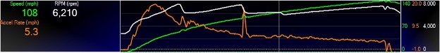
Note the rpm’s settle about 300rpm when the converter locks – noted by the white vertical line on the chart. This keeps the engine better focused in its power band, and the converter slip (and associated inefficiency) are eliminated for the second half of the run. Disregard the spikes in the Accel Rate – the vehicle speed used to calculate that arbitrary value was subject to wheelspin on the gear shifts causing those erroneous data points.
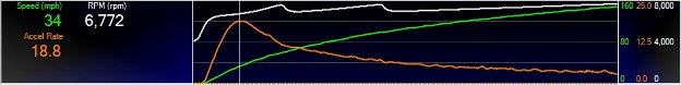
This data represents the culmination of perfect gear and converter selection. Off the line the converter flashes nearly instantly to 6000rpm – well into this high rpm combinations power band, and rockets the car off the line with the torque multiplication. One second into the run acceleration peaks, and then the converter slippage drops away as the RPMs rise to 7600rpm shift points, recovering on upshifts to 7000rpm. This converter setup would be considered very aggressive and essentially race-only, but serves as a great example of exactly how proper selection really focuses and keeps the engine in the meat of its power.
OTHER CONSIDERATIONS:
Of course there are hundreds of other scenarios beyond the specific examples laid out above that will influence gearing choice. A power adder can dramatically alter the low end torque output, to the point where you could over-gear the car and create traction issues. 6L80 cars, with their aggressive 4.03:1 first gear ratio are particularly susceptible to this, and likely pair best with the 3.45:1 final drive ratio from the manual transmission 10-15’ Camaro SS.
Then there are also practical considerations such as longevity. Our example car’s 218mm/8.6” rear differential unit does not have a good reputation for strength. This reputation is due largely in part to failures in stick shift applications. Automatic cars spare the driveline from the incredibly violent dynamic shock loads that stick shift cars generate, and so the OEM rear differential has a much better survival rate behind an automatic transmission. Still, sometimes a change to a ZL1 3.73 or 3.23 rear end is made in favor of strength, even at the expensive of running an ideal gear ratio.
On the drive-ability front consider a 6L80 with 3.91s is twisting almost 2,400rpm at 75mph – by no means extreme but will definitely reduce cruising MPGs a bit. Typically, cruising mileage is a concern secondary to performance for these application, and is considered a practical trade off.
CONCLUSION:
As you can see, there are many factors that influence choice in a torque converter and final drive ratio change. These changes have a profound impact on feel and performance and are one of the best modifications you can do to improve the performance (and often drive-ability) of your late model hot rod. If you’re still not sure about what’s right for you, feel free to reach me at andrew@gwatneyperformance.com – we’ll get you sorted out in no time!

I have a 2015 SS with a automatic and really wanted to get the 4:10 gears but you never really touched on those gears in a automatic car. Eventually after the warranty is expired I want to get a pretty big cam and stall converter. I drive on the street, like to race stoplight to stoplight and the occasional dragstrip days so fuel economy is not my concern. Was just curious if there was a reason for not talking about the 4:10’s in the automatic street cars. I really had my heart set on it, but if it is going to hurt me I’d like to know before I buy the 4:10’s
I put 3.73 gears in a2010 Camaro ss also 1/78 long tube headers and cai I bought a 3200 to3400 stall converter because later I’m putting a cam in but till then do I need the converter in there now to run better.
The increased stall speed will benefit a bolt on car like you have now. The stall speed really needs to be aligned to the camshaft and intake manifold combination you end up running, as that dictates the operating range of the combination and where the peak torque occurs. 3200-3400 is fairly mild – so if you have an appetite for a moderate to aggressive camshaft I would consider more stall speed. There is no reason you can run a 4000rpm stall in a bolt on car – it will actually perform very well, and that makes for a good fit with bigger “stage 3-4” cam when you reach that point.